ANPRO Stainless Installation 15 - 168 mm
This installation page is rebuilt for ANPRO using the structure and technical rhythm of a press-fit install guide, while keeping the presentation in ANPRO's own red, black, and white brand language.
Installation steps, ring seal checks, press tool guidance, and fitting clearance references are organized here as a practical front-end guide instead of a flat PDF upload. Legacy ANPRO tooling images from the old technical page are used throughout as supporting visuals.
Installation Workflow
This sequence follows the same practical order as a stainless press-fit install sheet: select the correct press tool, prepare the tube properly, confirm ring seal suitability, mark insertion depth, complete the press, and finish with a visual check.
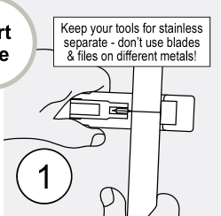
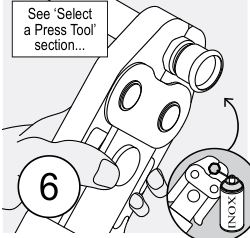
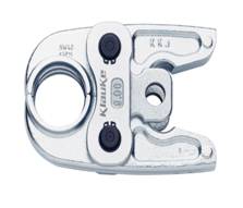
Select The Press Tool
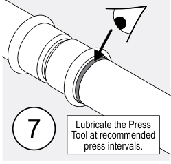
Use a press tool, jaw, or collar to suit the fitting, dimension, and application pressure. Keep stainless tooling separate and ensure the press zone is properly lubricated at recommended intervals.
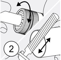
Cut To Length
Cut the tube square using an inox-suitable cutter or blade. For larger sizes, use a stainless rotary cutter or thin grinder disc that is reserved for stainless work.
Deburr The Tube
Deburr both the inside and outside edges of the tube end so the ring seal is not cut during insertion. For larger sizes, use a smooth half-round file reserved for stainless.
Inspect Fitting & Ring Seals
Confirm the rubber ring seal is undamaged, the correct type and colour for the application, and free of debris before the joint is assembled.
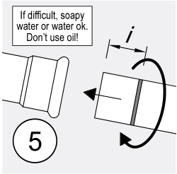
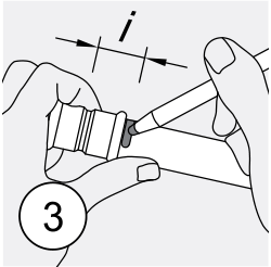
Mark Insertion Depth
Measure and permanently mark the insertion depth from the end of the tube using the socket depth "i" so the final pressed joint can be checked visually.
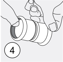
Join Tube & Fitting
Insert the tube into the press socket, turning slightly until the previously marked insertion depth reaches the end of the fitting socket.
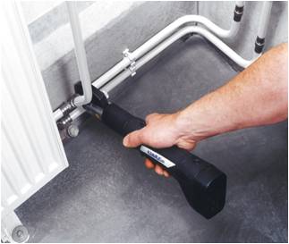
Press The Joint
Complete the press with the correct jaw, ring, or collar combination for the selected dimension. Read and follow the tool manual before operation.
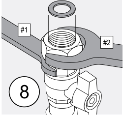
Check The Press
Visually inspect the pressed fitting and confirm the insertion mark is aligned with the end of the socket. For threaded ends, support the fitting and do not tighten against the pressed joint alone.
Ring Seal Selection
The installation guide should make seal suitability visible before the contractor starts work. Different ring seals are intended for different service conditions and should never be mixed without checking the application first.
EPDM Ring Seal
For potable water applications and temperature range -20 to +100°C.
hNBR Ring Seal
For gas applications including natural gas and LPG where the correct gas-rated seal is required.
FKM Ring Seal
For high-temperature duties plus certain oils and chemicals, subject to suitability confirmation before installation.
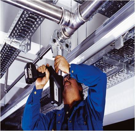
Legacy Technical Installation Images
The old ANPRO technical page carried a dedicated installation and tooling section. Those archived images are reused here as ANPRO-branded support visuals for the installation guide.

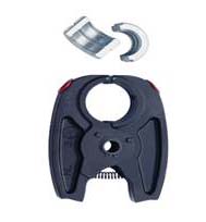
Klauke - ANPRO I-Press
Legacy technical images for the UAP3 press machine range used around 12 mm to 54 mm sizes.

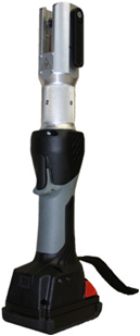
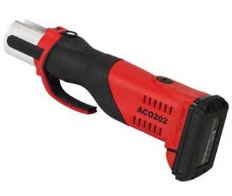
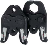
V-tech Machines
Legacy V-tech machine visuals shown in the old ANPRO technical section for approximately 12 mm to 35 mm installation use.
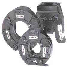

Novopress Supersize Machines
Legacy supersize press tooling images from the old ANPRO technical page for larger-diameter installation support.
Press Tool Options & Pressure Direction
The install guide should state clearly that tool choice depends on dimension, fitting, and application pressure. The pressure notes below follow the same grouped logic used in a stainless install sheet.
15 mm to 22 mm
The small-size path stays on the most direct jaw workflow, so the layout can be kept clean and easy to scan for installers on site.
Use the matched jaw size for daily installation work on compact dimensions.
Minimal setup changes when the installer stays inside the direct jaw range.
Confirm tool family, jaw condition, and approved pressure before starting.
Smaller size standard press route
This group remains in the easiest 32 kN installation band, so the interface focuses on quick confirmation instead of dense manual text.
28 mm to 35 mm
This band begins to split between direct jaws and matched ring support, so the panel now expands into a clearer two-path summary.
Direct jaw work remains common, especially where a full matched jaw set is available.
Use an approved ring path when the chosen tool family requires it.
Do not mix unsupported rings, adaptors, or pressure classes across tool brands.
Mid-small group with mixed tooling logic
Pressure capability remains within the standard installation band, but tooling approval becomes more important as size increases.
42 mm to 54 mm
This is where adaptor logic becomes normal, so the interface gives the installer a more explicit workflow instead of a long paragraph.
Common when direct jaw coverage is not available for the full size group.
Use only where the installation sheet and tool family both support the ring arrangement.
Review pressure path, jaw seat, and ring/adaptor match before every press cycle.
Adaptor-led route with tighter approval control
At this range, the jobsite must confirm the exact adaptor route early, because pressure approval depends on the full tooling combination.
66.7 mm to 108 mm
Large stainless sizes move into ring and adaptor territory, so this expanded state emphasizes the sequence of tooling decisions and pressure direction.
Large sizes are usually handled through ring-based pressing rather than one-piece direct jaws.
Choose the correct accessory path to match the selected press tool family.
Make sure site access, ring orientation, and tool rating all support the intended joint.
XL route with assisted tooling
This size group should be treated as a larger-system branch, where every press cycle depends on the correct ring, collar, and adaptor path.
139.7 mm to 168.3 mm
The largest branch is now shown as a dedicated heavy-duty route so the page feels controlled, readable, and consistent with the rest of the installation guide.
Use the dedicated heavy-duty tooling path for large diameter pressing.
Check lifting, access, and collar seating before the press cycle begins.
Match collar system, tool head, and rated pressure to the final installation specification.
Large collar route with high-force tooling
This branch should feel distinct from the smaller groups: more force, more clearance planning, and stricter approval control for every component.
Fitting Clearances
These insertion depth and clearance values are presented as a jobsite guide. Actual fitting dimensions and tool combinations should still be confirmed before final installation.
| D1 | Profile | i | L | A | D2 | B | C | D |
|---|---|---|---|---|---|---|---|---|
| 15 | M | 22 | 50 | 10 | 23 | 85 | 35 | 55 |
| 18 | M | 23 | 52 | 10 | 26 | 81 | 35 | 56 |
| 22 | M | 23 | 52 | 10 | 32 | 95 | 35 | 56 |
| 28 | M | 26 | 56 | 10 | 38 | 107 | 35 | 58 |
| 35 | M | 29 | 72 | 20 | 45 | 121 | 35 | 61 |
| 42 | M | 32 | 80 | 20 | 54 | 147 | 35 | 65 |
| 54 | M | 37 | 90 | 20 | 66 | 174 | 35 | 70 |
| 66.7 | M | 51 | 118 | 20 | 84 | 173 | 35 | 84 |
| 76.1 | M | 54 | 126 | 20 | 95 | 223 | 75 | 128 |
| 88.9 | M | 61 | 136 | 20 | 110 | 249 | 75 | 135 |
| 108 | M | 82 | 158 | 20 | 133 | 292 | 75 | 150 |
| 139.7 | M | 98 | 256 | 60 | 165 | 332 | 70 | 168 |
| 168.3 | M | 121 | 302 | 60 | 195 | 456 | 70 | 191 |
Project References
Installation guidance stays focused on workflow, tooling, and clearances. The full ANPRESS 316L project references now live on a dedicated page so the case material can expand without interrupting the install sequence.
Open the full References page
The separate References page now carries the complete project case write-ups for Yishun, Jurong, Tuas, and Punggol. It is the right place to show public-sector housing, infrastructure, and industrial-use positioning for ANPRESS stainless 316L.
Use it when a consultant, contractor, or distributor wants project-facing proof points instead of installation instructions.

Floral Spring @ Yishun

Punggol Crest
Tuas Bay Drive
Site Notes
Use this page as the ANPRO installation menu entry for field support, tool preparation, and dimension guidance. It is designed to be more readable than a PDF while still carrying the same practical structure installers expect.